.png?width=237&name=pid%20(1).png) The industrial sector is heavily reliant on PID controllers for all sorts of automation needs. A control loop is a fundamental feedback mechanism that is put in place to bridge the gap between the measured process variable and the desired set-point. Controllers are used to apply the appropriate corrective efforts through interfaces called actuators that can drive the variable up or down. The controller applies the corrective effort in a loop, until the error is eliminated up to the desired accuracy.
The industrial sector is heavily reliant on PID controllers for all sorts of automation needs. A control loop is a fundamental feedback mechanism that is put in place to bridge the gap between the measured process variable and the desired set-point. Controllers are used to apply the appropriate corrective efforts through interfaces called actuators that can drive the variable up or down. The controller applies the corrective effort in a loop, until the error is eliminated up to the desired accuracy.
History
When the first feedback controllers came into production, they were only designed with the proportional term. However, soon it was realized that P-only controllers were only able to drive the error downwards to a negligible but still, a non-zero value. This required the operators to manually set the gain until the last trace of error was removed.
To perform this last bit of action automatically, the integral term was introduced, and often called automatic reset due to its ability to adjust the proportional action. Shortly thereafter, the derivative term was introduced and was described as a rate control, acting as a crude predictor of errors that may happen based on the current slope of error.
PID Basics
A PID Controller makes use of the following formula to calculate its output, i.e. u(t), whereas e(t) is the error signal, which is the difference between the process variable & the set-point.

PID Controllers have a couple of terms associated with them; these include:
- Gain – this refers to the percentage by which the error signal gains or loses strength as it passes through the various blocks of the controllers, all the way to the output. For instance, if a PID controller is set to high-gain, it would carry out corrective efforts in an aggressive manner for the removal of the error.
- Integral Time – A hypothetical set of events may cause the error signal to abruptly jump to a fixed value which would illicit an instant response from the controller’s proportional term as well as a steadily increasing response from the integral term. The time it takes for the integral term to catch up to the unchanging proportional time is the integral time and is denoted by TI.
- Derivative Time – If an error starts at zero and increases at a fixed rate then the proportional term would also start at zero, whereas the derivative term would assume a fixed value. The derivative time, TD is a measure of the relative influence of the derivative term, meaning a PID controller with a long derivative time would execute a heavier derivative action than a proportional one.
Loop Tuning
Often referred to as an art, loop tuning a PID controller means selecting values for the tuning parameters, i.e. P, TI, and TD so that the controller would be able to eliminate the error in a respectable amount of time, without causing too many fluctuations.
A car’s cruise controller provides a fine example of this. Whenever a car starts, its inertia adds a delay between the time the accelerator was pushed and the time when the desired speed is reached. The controller’s derivative & proportional actions in this case must not kick in instantly but in a manner that wouldn’t be too uncomfortable for the passengers or hard on the internal machine parts. If the delay in reaching the desired speed is too long, the integral action would also kick-in, and dominate the controller’s output.
Setting the three parameters isn’t an easy thing to do as all three are interdependent, which means modifying one of them would affect the performance of the other two as well.
Ziegler-Nichols Tuning
In 1942, John G. Ziegler and Nathaniel B. Nicholas, who worked at Taylor Instruments, devised an interesting methodology of dealing with loop tuning problems.
Their open loop technique involves putting the controller through an offline step test, after which a curve called reaction curve is plotted based on the results. At the curve’s steepest point, a tangent is drawn that provides information as to how fast the process reacts to a step change. Both reached the following conclusion:
- The process time constant, T, is the inverse of the tangent line’s slope.
- The dead time, d, is the time taken by the process to demonstrate its initial reaction to the step.
- The process gain, K, denotes how much the process variable increases with respect to the size of the step.
Ultimately, Ziegler & Nicholas devised formulas that provided them with values for the three parameters, i.e. P, TI, and TDfrom T, d and K. The formulas are:
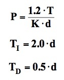
Once these parameters are loaded onto the PID formula, and the controller is put in automatic state, no further interruptions are required for eliminating errors or fluctuations.
Still, PID loop tuning isn’t a simple process, and requires reiterations whenever the nature of the process changes in any manner. This is why loop tuning is referred to as an art and requires a combination of experience & luck, rather than raw mathematical skills!
Interested in learning more? Talk to one of our professionals at PanelShop.com.